Critical Oil Flowrate for Gas Coning


This Excel spreadsheet uses the Mayer and Garder correlation to calculate the oil flowrate necessary to form a stable gas cone in an oil and gas reservoir.

Gas coning references the tendency of gas to flow in the direction in which its face the least resistance, against the flow of gravity.  Above the critical oil flowrate, the cone will breakthrough and gas will force the oil flow downwards towards the well perforation.  At this point, gas will tend to dominate crude oil production (often to the point where the well is not economically feasibile).

Gas coning is often significant if an oil reservoir is in contact with an aquifer or gas cap.

The critical oil flowrate is sometimes lower than the economical production rate, but techniques have been developed to combat gas coning (including using horizontal wells instead of vertical wells, and infill drilling)

The Mayer and Garder equation and a screengrab of the spreadsheet are given below.


  • ρo and ρg are the densities of the oil and gas in lb ft-3
  • re and rw are the drainage radius and welbore radius in ft
  • Bo is the oil formation volume factor (this is almost always above 1)
  • μo is the viscosity of the oil in centipoise
  • ko is the effective oil permeability
  • Q is the oil flowrate in stb day-1

  • Calculate Original Gas in Place with Excel

    This Excel spreadsheet calculates the Original Gas in Place with a p/z plot.  Specifically, this spreadsheet fits the observed p/z data and cumulative gas product to the following curve

    where
    • (p/z) is the observed values of pressure over compressibility (collected during the life of a reservoir)
    • Gp is corresponding cumulative gas production (again collected during the life of a reservoir)
    • (p/z)i is the initial value of pressure over compressibility of the system
    • G is the original gas in place
    This equation is simply a material balance, which many engineers use to determine the Original Gas in Place in volumetric natural gas reservoirs. It assumes a constant pore volume and includes the effect of gas expansion.  Note that the equation predicts a linear relationship between p/z and G

    This screen grab illustrates the contents of the spreadsheet.


    The spreadsheet is easy to follow.  It simply minimizes the sum-square residuals (difference between predicted and actual values of p/z) by varying G.  You can also choose to vary (p/z)i in addition to G to minimize the sum-square residuals, but since this value is usually accurately measured, this is not recommended.

    Fundamentally, this method is pretty simple to understand - we're simply locating the intercept on the x-axis (where p/z = 0) of a straight line fit of G against p/z, as illustrated by this picture.


    This method of determining the Original Gas in Place is only suitable for normally pressurized gas reservoirs, where the gas expansion is the only significant factor contributing to gas production. This method, however, is not suitable for abnormally-pressurized reservoirs, where gas production is affected by formation compressibility (i.e.the expansion of sand, rock and water). Gas reservoirs are often abnormally-pressurized if they are in contact with aquifers

    Model a Gas Orifice Meter with Excel

    This Excel spreadsheet calculates the flowrate from the pressure drop across a gas orifice meter with the equations defined in ISO 5167.

    Orifice meters use the pressure loss across a constriction (that is, the orifice plate) in a pipe to determine the flowrate.  While orifice meters are cost effective, they have several disadvantages. 
    • The relationship between flowrate and pressure is non-linear,
    • accurate values of the physical parameters are required,
    • and high Reynolds numbers (>104) are required for the greatest confidence in their accuracy, and the resulting pressure drop can be significant.
    Accordingly, orifice meters are only used with the pressure drop is not critical, and accuracy is around 2% at best.

    These are the equations implemented in the spreadsheet (as specified in ISO 5167)

    Gas Orifice Meter Equations in ISO 5167

    The notation is given below
    • C is the discharge coefficient (only valid for the three standard tap positions given below)
    • Re is the Reynolds number
    • L1 and L2 are the upstream and downstream tap positions (m)
    • P1 and P2 are the upstream and downstream pressures (Pa)
    • D1 and D2 are the pipe and orifice diameters (m)
    • V is the gas velocity in the pipe (m s-1)
    • ρ is the gas density (kg m-3)
    • μ is the gas viscosity (Pa s) 
    • M is the molecular weight
    • Y is the expansion coefficient
    • Z is the gas compressibility factor
    • K is the specific heat ratio
    • R is the gas constant (8314 J kg-1 k-1)
    • Ao is the cross-sectional area of the orifice (m2
    There are three standard tap positions that determine the values of L1 and L2, as illustrated below. For corner taps, L1 = L2= 0, for D-D/2 taps L1 = D1 and L2= D1/2, and for flange taps L1 = L2= 1 inch. 
    Tap positions in ISO 5167

    The equations use the ideal gas law to calculate the gas density (you could override this with your own value), and are only valid for pipes with internal diameters from 50 mm to 1000 mm, and for pressure ratios greater than 0.75.

    This is a screen grab of part of the spreadsheet.


    The calculation is iterative: you need Re to calculate C, you need V to calculate Re, but you need C to calculate V.  Excel's Goal Seek functionality is used to iteratively solve the equations for the flowrate. This process is automated with a button - just fill in the parameters, click a button, and some VBA initiates Goal Seek with the correct settings

    The spreadsheet provides an initial guess value for Re. This is used to calculate C and V. V is then used to calculate Re.  Excel's Goal Seek varies the guess value of Re until it matches the calculated value of Re.

    By carefuly altering the equations (and the parameters used by Goal Seek), you could also solve for any other variable - for example, you could find the pressure drop for a specific flowrate (let me know if you need help in implementing this).

    You'll find a spreadsheet  that models a liquid orifice meter here.

    Visit http://excelcalculations.blogspot.com regularly for more free engineering spreadsheets.

    Download Excel Spreadsheet to Calculate Flowrate in a Gas Orifice Meter (ISO 5167)

    Size a Liquid Orifice Meter with ISO 5167 and Excel

    This Excel spreadsheet sizes a liquid orifice meter using the equations in ISO 5167.  Orifice meters determine liquid flowrate by measuring the pressure difference across a constriction in a pipe. 

    The spreadsheet is free - all I ask is that you credit this website with its authorship (and perhaps provide a link!)


    The equations given in ISO 5167 are given below.
    • C is the discharge coefficient (the equation is only valid for the three standard tap positions defined below)
    • Re is the Reynolds number
    • L1 and L2 are the upstream and downstream tap positions (ft)
    • P1 and P2 are the upstream and downstream pressures (psig)
    • D1 and D2 are the pipe and orifice diameters (inches)
    • V is the liquid velocity in the pipe (ft s-1)
    • ρ is the liquid density slugs ft-3
    • μ is the liquid viscosity lb-sec ft-2

    ISO 5167 defines three different tap positions for the pressure probes (Corner, D-D/2 and Flange taps). These positions the values of L1 and L2, and are given below

      • Corner Taps: L1 = L2 = 0
      • Flange Taps: L1 = L2 = 1 inch
      • D-D/2 Taps: L1 = D1, L2 = D1/2
      The solution to the equations is iterative; you need Re to calculate C, but you need Q to calculate Re, but you need C to calculate Q.  This requires the use of Excel's Goal Seek.  We simply find the
      1. Guess a value of Re,
      2. Calculate C and Q
      3. Use C and Q to calculate Re
      4. Use Goal Seek to change the value of Re we guessed in Step 1 until it's equal to the value calculated in Step 3
      This process is automated in the Excel spreadsheet with a button linked to a VBA macro. The VBA macro simply initiates Goal Seek with the requireed settings.

      Download Excel spreadsheet to size an orifice meter with ISO 5167

      Compressibility Factor Calculator for Excel

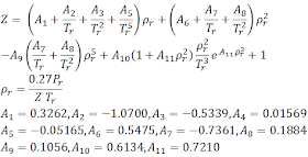
      This Excel spreadsheet calculates the compressibility factor for natural gas using the Dranchuk-Abou-Kassem correlation.  Engineers need the compressibility factor to calculate natural gas flowrates (e.g., using the Weymouth Equation), viscosities (e.g. using the Lee, Gonzalez and Eakin correlation) or other properties


      Tr is the reduced temperature, Pr is the reduced pressure, and ρr is the reduced density. The correlation is only valid for 0.20 ≤ Pr < 30, and 1.0 < Tr ≤ 30. The constants A1 to A11 were found by a best−fit to the Standing and Katz chart with an average absolute error of 0.585%.


      The Dranchuk-Abou-Kassem equation is implicit; solving for Z requires an iterative solution method.  Several several methods exist in Excel, and the spreadsheet demonstrates two of these methods.
      • A circular reference.  Make sure File>Options>Formulas>Enable iterative calculation is checked)
      • Goal Seek.  Here we 
        • guess a value for Z 
        • use this to calculate ρr
        • use ρr calculate Z
        • use Goal Seek to minimize the difference between the guess and calculated values of Z by varying the guess value of Z
      I've found that the result given via Goal Seek is more numerically stable (the circular reference often gives unrealistic results).  There's a button in the spreadsheet to initiate Goal Seek.

      If you want Goal Seek to automatically recalculate the compressibility factor whenever the reduced temperature or pressure are changed, add this VBA to Sheet1 in the spreadsheet.

      Private Sub Worksheet_Change(ByVal Target As Range)
      Dim bSuccess As Boolean
          On Error Resume Next
          bSuccess = Range("diff").GoalSeek(0, Range("guessz"))
          On Error GoTo 0
          If Not bSuccess Then
              MsgBox "Goal Seek Failed for Compressibility Factor"
          End If
      End Sub

      You may also want to check out this Excel spreadsheet which uses the Beggs and Brill correlation to calculate the compressibility factor of natural gas.

      Download Excel spreadsheet to calculate the compressibility factor with the Dranchuk-Abou-Kassem correlation

      Calculate Erosional Velocity with Excel

      This Excel spreadsheet helps you calculate erosional velocity in Excel.  The offshore oil industry often requires the transport of liquid, gas and solids in long distance pipelines.  This causes the pipe surface to erode, with the rate of erosion increasing with the flow velocity.

      The American Petroleum Institute have guidelines (see API RP14E) for the flow velocity below which erosion damage is minimized.  This maximum flow velocity is a function of velocity and density, and given by this equation.
      where ρ is the gas/liquid density at the flow temperature and pressure, C is an empirical constant, and V is the maximum recommended velocity. This equation is only valid for horizontal flow with shear stress as the limiting factor

      If ρ is in lb ft−3 and V is in ft s−1, then C has units of lb0.5 ft−0.5 s−1. API RP14E recommends that C=100 lb0.5 ft−0.5 s−1 for continuous service of liquid with solids, or C=125 lb0.5 ft−0.5 s−1 for intermittent service (or values of up to 200 lb0.5 ft−0.5 s−1 if the pipelines are corrosion resistant).

      However, recent studies have recommended that higher C values are used, with values of 887 for 13Cr piping for "clean gas service" (see the paper "Improved Procedures for Estimating the Erosional Rates in High Offtake Gas Wells: Applications of University of Tulsa Flow Loop Derived Correlation" for more detail).


      This Excel spreadsheet implements the API RP14E equation to calculate erosional velocity.  If you enter the specific gravity of the liquid and gas components, the gas/liquid volume ratio, the the absolute temperates and pressures, and the compressibility factor, the Excel spreadsheet will calculate the mixture density for you.  Note that the spreadsheet expects all values to be in SI units, including the erosional velocity coefficient C (a conversion factor is supplied in the spreadsheet).

      Calculate Viscosity of Natural Gas with Excel

      This Excel spreadsheet will calculate the viscosity of natural gas. The spreadsheet uses the Lee, Gonzalez and Eakin correlation for the viscosity, and the CNGA (California Natural Gas Association) correlation for the compressibility factor.

      The Lee, Gonzalez and Eakin correlation, only requires the pressure, temperature and molecular weight of the natural gas, and is relatively accurate compared to more complex methods of predicting viscosity.  It still widely used and accepted.

      The CNGA compressibility factor correlation is suitable for pressures above 100 psig (below 100 psig, the compressibility factor is 1)
      The Lee, Gonzalez and Eakin correlation was published in 1964 and accurately predicts the viscosity of natural gases with low non-hydrocarbon content, and for temperature between 100 F - 340 F, and pressures between 14.7-8000 psia. Additionally, the correlation is only suitable for sweet gases, and does not accurately describe sour gases (as described in this paper). The correlation has standard deviation of 2.7%, with a maximum deviation of 8.99%. The correlation is


      Gas density is predicted by this correlation.

      where ρ is the density in g/cm3, P is the pressure in psig, MW is the molecular weight (lb/lbmol), R is the gas constant (10.731 ft3 psi °R−1 lb-mol−1), T is the absolute temperature (°R) and Z is the compressibility factor.

      Calculate Bottom Hole Pressure with the Cullender and Smith Method

      This Excel spreadsheet employs the Cullender and Smith method to calculate Bottom Hole Pressure on a shallow, dry gas well. The bottom hole pressure is simply the pressure at the bottom of an oil-well shaft

      Many reservoir engineering calculations require the static bottom hole pressure.  However, this can be difficult to measure experimentally. A number of researchers have developed other techniques to calculate bottom hole pressure from measurements at the wellhead.

      The Cullender and Smith (1956) method is generally considered accurate and models the variation of compressibility Z with temperature T and pressure P

      This is the Cullender and Smith equation

      It needs to be numerically integrated. In the attached spreadsheet, we have simply divided the entire length into four sections and integrated via a simple trapezoidal method.

      Calculate Least Cost Pipe Diameter and Flow Velocity with Excel

      Generally, engineers choose pipe diameters and flow velocities which minimize the total cost of the pipeline over the whole pipeline lifecyle.  The total cost is the sum of the capital costs and operational costs. 

      This Excel spreadsheet calculates the least total cost pipe diameter and flow velocity for a pipe, given the desired construction material, flowrate, viscosity and density.


      It uses the Generaux Equation and the empirical cost parameters as given the in the January 2010 article in Chemical Engineering "Updating the Rules for Pipe Sizing".  The Generaux Equation is an empirical correlation that takes into account the
      • annual depreciation and maintenance for the pipe
      • annual depreciation of the associated pumping equipment
      • installed cost of the pipe
      • fractional efficiency of pump
      • installation and fitting costs
      • energy cost to power the pump motor
      • friction in the pipe fittings
      • installation cost of the pump
      • cost of the pipe
      • number of operating days per year
      • taxes and other expenses
      • fluid density, viscosity and the desired flowrate
      The calculation is iterative and uses Excel's Goal Seek Functionality.  

      The spreadsheet enables you to choose from empircal cost parameters for 1998 and 2008, for a range of materials. Generally, least-cost flow velocities have decreased over time because energy costs have increased.

      Instructions
      1. Specify the construction material (choose either Carbon Steel, Stainless Steel, Alumimum or Brass), fluid density and fluid viscosity
      2.  Click the Optimize button to initial Excel's Goal Seek function